
The terms “idler sprocket” and “drive sprocket” appear throughout chain drive engineering literature, but their precise meanings and the boundaries between their functional roles are often left vague. In a simple two-sprocket drive, the distinction is straightforward: one sprocket inputs power, the other receives it. In real industrial machinery — conveyors with multiple driven points, overhead systems with route-changing idlers, agricultural equipment with complex multi-shaft power distribution — the same physical sprocket can function as a drive element in one part of a system and as a passive support or tensioning element in another. Getting the terminology and engineering correct for each role matters for correct specification, load calculation, and maintenance planning.
The Drive Sprocket: Definition and Engineering Characteristics
A drive sprocket — also called a driver, driving sprocket, or input sprocket — is any sprocket that inputs mechanical power into the chain. In a simple two-sprocket drive, the drive sprocket is on the input shaft (motor, engine, or gearbox output). In a multi-shaft conveyor, the drive sprocket is at each point where a motor applies torque to the chain. The drive sprocket experiences the highest loads of all sprockets in the drive, because it carries the full tight-side chain tension as the chain wraps from the output shaft around the tooth engagement arc. Heavy duty roller chain sprockets in main-drive applications are drive sprockets by definition, and their specification must account for the full transmitted torque plus all dynamic load factors.
Engineering Implications for Drive Sprocket Selection
Drive sprockets are specified for tooth count, pitch, bore, material, and tooth hardness based on the full transmitted power. The calculation path is: torque → tight-side chain tension → chain selection at the required chain tension and speed → sprocket tooth count selection for the required speed ratio. Tooth hardness on drive sprockets matters more than on idler sprockets because the tight-side load produces higher contact stress between the chain roller and the tooth seat on the drive sprocket than anywhere else in the drive.
The Driven Sprocket: Definition and Engineering Characteristics
The driven sprocket — also called the follower or output sprocket — receives power from the chain and transmits it to the output shaft. In a simple drive, the driven sprocket is always the larger of the two sprockets in a speed-reducing configuration (or smaller in a speed-increasing drive). The driven sprocket experiences the same chain tension as the drive sprocket, but because the driven sprocket typically rotates more slowly (in a speed-reduction drive), the power transmitted per revolution at the driven shaft is higher (torque × speed = constant power). Drive chain sprockets at the driven end of conveyors and agricultural drives must be selected for the full transmitted load including any speed-ratio-driven torque multiplication.
The Idler Sprocket: Definition and Engineering Characteristics
An idler sprocket is a sprocket that engages the chain without being connected to a driving or driven shaft in the power transmission path. It does not input or extract power. Its function is to redirect, tension, support, or increase the wrap angle of the chain. As described in our companion article, double pitch chain sprockets in overhead conveyor systems are frequently used as both drive elements and as idlers in the same conveyor, depending on position in the layout.
From a load calculation standpoint, an idler sprocket carries a chain contact force equal to the vector sum of the chain tensions on both sides of the idler — which is less than the tight-side tension on a tensioning idler positioned on the slack side, but can exceed the tight-side tension on an idler that creates an additional bend in the chain path. This contact force is a radial load on the idler shaft bearing and must be included in the bearing selection for the idler shaft.
Side-by-Side Comparison: Drive vs. Driven vs. Idler
| Parameter | Drive Sprocket | Driven Sprocket | Idler Sprocket |
|---|---|---|---|
| Power role | Inputs power to chain | Extracts power from chain | No power exchange; directional or tensioning only |
| Chain tension | Tight-side tension on output arc | Tight-side tension on input arc | Vector sum of both span tensions |
| Shaft connection | Keyed to driving shaft (motor/engine) | Keyed to driven shaft (machine load) | Free-running on fixed shaft (bearing mounted) |
| Keyway requirement | Yes — must transmit torque | Yes — must transmit torque | No — plain bore or bearing bore only |
| Tooth hardness priority | Highest — highest contact stress | High — full chain tension | Lower — only directional force applied |
| Speed | Input shaft speed | Output shaft speed (ratio-determined) | Matches local chain speed at contact point |
| Material selection | Full specification for operating environment | Full specification for operating environment | Same corrosion/hygiene requirements as drive sprockets |
| Hub type | Type B or C (torque transmission) | Type B or C (torque transmission) | Type A or plain bore acceptable |
Placement in Drive Layouts: Where Each Type Goes
In a basic horizontal chain drive, placement is obvious. In real machinery layouts, the engineer must identify which sprocket carries which functional role at each location in the drive topology before selecting tooth count, bore, and material.
Common Specification Errors When Confusing Drive and Idler Roles
The most frequent errors in chain drive design and procurement arise from incorrectly classifying sprockets as idlers when they are actually drive or driven elements, or from applying idler-level specification to drive sprockets.
Selecting the Right Specification for Each Role
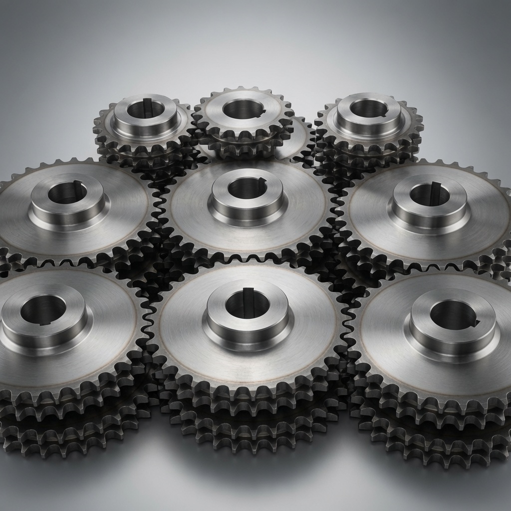
The selection criteria for drive and driven sprockets are determined by the full transmitted load calculation. Idler sprockets are selected primarily by tooth count (enough to prevent excessive chordal action), material (matching the corrosion and hygiene requirements of the environment), and bearing (sized for the actual radial load). For a complete range of industrial chain sprockets in all three roles — from small idler sprockets at No.25 pitch through large main-drive sprockets at No.100 pitch — contact our engineering team with your drive layout and we will specify the correct tooth count, bore, and material for each position.
Hangzhou Ever-Power manufactures stainless steel, carbon steel, and custom chain sprockets for global industrial buyers. Low MOQ, full documentation, fast lead times.
SHENHUA ROAD, HANGZHOU, CHINA | +86-571-88220653