
The taper lock bushing system is one of the most useful and widely misunderstood power transmission components in industrial machinery. Walk through any well-equipped machine shop or maintenance store and you will find taper lock bushings alongside gears, pulleys, and sprockets — yet many engineers who use them daily have never consciously thought through why the taper lock concept works, why it is better than a simple keyway for many applications, and what specific installation steps determine whether a taper lock assembly holds securely for years or loosens under the first shock load. This article answers all three questions in detail.
What Is a Taper Lock Sprocket? Components and Concept
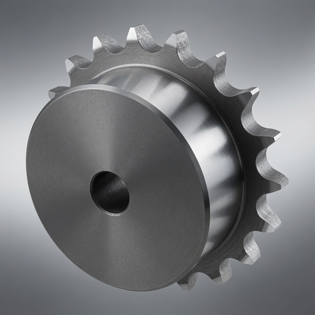
A taper lock sprocket is a sprocket that accepts a separate taper lock bushing in its hub bore, allowing the sprocket to be mounted on shafts of different diameters without requiring a different sprocket for each shaft size. The bushing is a split, tapered sleeve that slides into a matching tapered bore in the sprocket hub. When the bushing flange bolts are tightened, the tapered outer surface of the bushing pulls into the tapered bore of the sprocket hub, compressing the split bushing around the shaft and locking the entire assembly — sprocket, bushing, and shaft — into a single rigid unit. Our stainless steel sprocket range includes sprockets pre-bored for standard taper lock bushing designations across all common chain pitches.
The taper lock system was developed in the mid-20th century as an alternative to the traditional method of boring each sprocket to a specific shaft diameter with a keyway and securing with set screws. The fundamental problem with the shaft-specific bore approach is inflexibility: a sprocket bored for a 1-1/2″ shaft cannot be fitted to a 1-3/4″ shaft without reboring, and a warehouse of sprockets must carry multiple bore variants of every tooth count and pitch combination. The taper lock system solves this by standardising the sprocket bore to a specific bushing designation, and offering each bushing in a range of shaft diameters — allowing one sprocket to serve many shaft diameters simply by changing the bushing.
Taper Lock Bushing Designations: How the System Is Organised
Taper lock bushings are identified by a standardised designation code that encodes two key dimensions: the nominal bore capacity and the flange outside diameter. Common designations include 1008, 1108, 1210, 1215, 1310, 1610, 2012, 2517, 3020, 3525, 4030, and 4535, among others. The first two digits give the bushing flange outside diameter in eighths of an inch; the last two give the maximum bore in eighths of an inch. A 2012 bushing has a flange of 20/8″ = 2.5″ outside diameter and accepts bores up to 12/8″ = 1.5″.
Each sprocket hub is designed to accept a specific range of bushing designations. A small sprocket at No.40 pitch with 15 teeth might accept 1008 or 1108 bushings; a large sprocket at No.80 pitch with 30 teeth might accept 3020, 3525, or 4030 bushings. The bushing designation range for each sprocket is listed in the catalogue and must be matched to the shaft diameter before ordering. The shaft diameter must fall within the bore range available for the bushing designation accepted by the sprocket.
| Bushing Designation | Max Bore (approx.) | Typical Sprocket Size Range | Typical Application |
|---|---|---|---|
| 1008 | 1″ | Small: No.25–No.40, 9–15T | Light conveyors, instrumentation |
| 1108 | 1-1/8″ | Small-medium: No.35–No.50, 12–20T | Packaging, food processing |
| 1210 / 1215 | 1-1/4″ – 1-7/16″ | Medium: No.40–No.60, 15–25T | General industrial conveying |
| 1610 | 1-3/4″ | Medium-large: No.50–No.80, 18–30T | Agricultural, medium conveyors |
| 2012 | 2-1/4″ | Large: No.60–No.100, 20–35T | Heavy industrial, combine drives |
| 2517 | 2-11/16″ | Large: No.80–No.100, 22–40T | Heavy conveyors, large agricultural |
| 3020 / 3525 | 3″ – 3-3/8″ | Very large: No.80–No.100, 25–50T | Mining, heavy industrial main drives |
The Taper Lock Mechanism: Why the Taper Holds
The self-locking property of the taper lock system is a direct application of wedge mechanics. When two tapered surfaces are pressed together with an axial force, friction at the interface prevents the wedge from backing out even when the axial force is removed — provided the taper angle is less than the friction angle for the material pair. Taper lock bushings use a taper half-angle of approximately 8°, which is below the friction angle for steel-on-steel contact (typically 10–15°), making the assembly self-locking: once drawn into the hub bore, the bushing stays locked without any additional mechanical retention.
The flange bolts on a taper lock bushing serve to draw the bushing into the hub bore during installation, not to retain it in service. This is a key conceptual distinction from set-screw retention: after installation, the flange bolts do no work in normal operation. The grip on the shaft is maintained entirely by the wedge self-locking force and the hoop stress in the compressed bushing sleeve. The bolts are then relocated to the removal holes (threaded holes in the hub flange that do not pass through the mating surface) and used only when the assembly needs to be released.
Step-by-Step Taper Lock Installation Procedure
Correct installation is the single most important factor in taper lock performance. The majority of taper lock failures — whether from slippage under load or inability to remove the bushing during maintenance — trace back to installation errors rather than design or material deficiencies.
Taper Lock Removal: The Correct Procedure
Removing a taper lock assembly is frequently attempted incorrectly, resulting in damaged hub bores or split bushings. The self-locking taper requires an axial force in the release direction — the same direction as installation — to break the wedge lock. Attempting to pry the hub off the bushing radially will damage the hub bore.
Taper Lock vs. Keyway and Set Screw: A Practical Comparison
The traditional alternative to taper lock mounting is a machined bore with keyway and set screws. Both methods are widely used for industrial chain sprockets, and each has genuine advantages in specific applications. The following comparison helps clarify which to choose for a given installation.
| Parameter | Taper Lock Bushing | Keyway + Set Screw |
|---|---|---|
| Shaft size flexibility | One sprocket serves multiple shaft sizes (change bushing) | One bore per shaft diameter |
| Axial holding force | Very high — self-locking taper | Moderate — relies on set screw friction |
| Torque transmission | High — through friction and keyway | Moderate — primarily through keyway shear |
| Installation speed | Moderate (6-step procedure) | Fast (slide on shaft, install key, torque screws) |
| Removal | Straightforward with removal bolts | Can be difficult if set screw corrodes |
| Concentricity | Excellent if correctly installed | Depends on bore machining quality |
| Shock load resistance | High — clamping force resists impact | Lower — set screws can loosen under shock |
| Cost | Higher (bushing + sprocket) | Lower (single machined part) |
| Best application | Variable shaft diameters; frequent removal/reinstallation | Fixed shaft diameter; permanent installation |
Hangzhou Ever-Power manufactures stainless steel, carbon steel, and custom sprockets for global industrial buyers. Low MOQ, full documentation, fast lead times.
SHENHUA ROAD, HANGZHOU, CHINA | +86-571-88220653