
Sprocket selection is one of those engineering tasks that appears straightforward until an experienced engineer lists out all the variables that must be correctly specified before an order is placed: chain standard, chain pitch, tooth count on both sprockets, bore diameter on both sprockets, keyway dimensions, hub type, material grade, surface treatment, and quantity. Miss or mis-specify any one of these and the result ranges from a sprocket that fits but wears prematurely to one that does not fit at all. This guide walks through the complete selection process in a logical sequence, explaining the engineering reasoning behind each decision so that the methodology can be applied to any chain drive, not just the specific examples used here.
Step 1: Define the Drive Requirements
Before selecting any component, the drive requirements must be established as precisely as possible. Vague requirements produce under-specified or over-specified components, and the cost of either error — in performance failure or unnecessary material expenditure — exceeds the time spent on a thorough initial specification by a wide margin. The following four parameters define any chain drive completely.
Step 2: Select the Chain Standard
The chain standard must be established before pitch selection because the available pitch options and the tooth form of the sprockets depend on the standard. For new designs, the choice is typically between ANSI (for North American market machinery and export to ANSI-standard markets) and DIN/ISO 606 (for European market machinery and export to DIN-standard markets). ANSI roller chain sprockets use inch-based pitches; DIN stainless sprockets use metric pitches derived from the British standard series.
Step 3: Select the Chain Pitch
Chain pitch selection involves balancing four factors simultaneously: load capacity (larger pitch = more load capacity per strand), chain speed (smaller pitch = better suited to high speed with less chordal action), sprocket size (smaller pitch produces smaller sprockets for the same tooth count), and cost (larger pitch chain and sprockets cost more per unit). The design process starts with the design power and speed, uses chain manufacturer load-rating charts to identify candidate pitch options, and then checks each candidate against the speed and centre-distance constraints.
| Chain Pitch (ANSI) | Typical Power Range (at 500 RPM driver) | Max Recommended Driver RPM (17T) | Suitable Drive Type |
|---|---|---|---|
| No.25 (1/4″) | Up to 0.5 kW | 4,000+ | Light instruments, food equipment |
| No.35 (3/8″) | Up to 2 kW | 2,500 | Agricultural feeders, vending |
| No.40 (1/2″) | Up to 7.5 kW | 2,000 | General industrial, packaging |
| No.50 (5/8″) | Up to 15 kW | 1,500 | Medium conveyors, agricultural |
| No.60 (3/4″) | Up to 30 kW | 1,000 | Heavy conveyors, main drives |
| No.80 (1″) | Up to 60 kW | 800 | Heavy main drives, combines |
| No.100 (1-1/4″) | Up to 100 kW | 500 | Very heavy main drives |
Step 4: Calculate the Tooth Count for Both Sprockets
With the speed ratio established from the input and output speed requirements, and the chain pitch selected, the tooth counts for drive and driven sprockets can be determined. The speed ratio equals the ratio of the driven sprocket tooth count to the driver sprocket tooth count: Ratio = N_driven / N_driver. For a 3:1 speed reduction with a 17-tooth drive sprocket, the driven sprocket has 51 teeth. For agricultural chain sprockets on a combine feeder drive with a 2.5:1 reduction and a 19-tooth driver, the driven sprocket has 47 or 48 teeth.
The minimum recommended tooth count for the drive sprocket is 17 teeth in most applications, to keep chordal action within acceptable limits at normal operating speeds. Using fewer than 17 teeth is acceptable for very slow drives (below 50 RPM) where chordal action is inconsequential, but should be avoided for any drive above 100 RPM. Using more than 17 teeth on the driver — 19, 21, or 25 — reduces chordal action and noise at the cost of larger sprocket diameters and longer chain spans.
Step 5: Select the Bore Size and Keyway
The bore diameter must match the shaft diameter to a precision fit. The standard practice for chain sprocket bores is H7 tolerance in metric systems (ISO 286) or the equivalent standard fit in inch systems — a bore that provides a clearance or light transition fit with the shaft diameter, allowing the sprocket to be pushed onto the shaft by hand or with light mallet force, and secured by a key and set screw or taper lock bushing.
The keyway dimensions are standardised to the bore diameter: DIN 6885A (metric) or ANSI B17.1 (inch) specify the standard keyway width and depth for each shaft diameter range. When ordering sprockets with custom bores and keyways, specify the bore diameter (in H7 tolerance), the keyway width, keyway depth, and whether the keyway should be at the centre of the hub or offset. Taper lock bore options eliminate the need to specify bore and keyway dimensions if the bushing designation is specified correctly.
Step 6: Select the Material Grade
Material selection for drive chain sprockets follows the decision framework established in the steel-versus-stainless comparison: C45 with HF hardening for dry, lubricated, indoor or outdoor agricultural applications; 304 stainless for food-grade, pharmaceutical, wash-down, and corrosive environments; 316L stainless for high-chloride or marine environments. The following simplified decision table covers the most common scenarios:
| Operating Environment | Recommended Material | Surface Treatment |
|---|---|---|
| Dry indoor, lubricated | C45 steel | HF quenching 40–50 HRC |
| Outdoor agricultural | C45 steel | HF quenching + light zinc coat |
| Food processing (wash-down) | 304 stainless steel | ASTM A967 passivation |
| Pharmaceutical/cleanroom | 304 stainless steel | ASTM A967 passivation |
| Marine/coastal outdoor | 316L stainless steel | ASTM A967 passivation |
| Chemical process (chloride-rich) | 316L stainless steel | ASTM A967 passivation |
| Light-load, self-lubricating zone | Acetal/nylon engineering plastic | None required |
Step 7: Specify Hub Type and Configuration
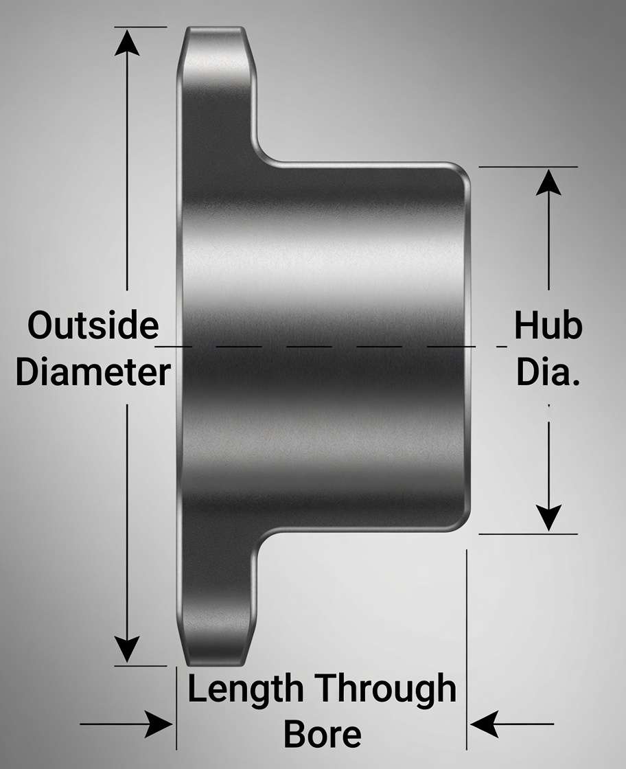
Hub type (A, B, or C) is determined by the shaft engagement length required for the applied torque and by the clearance constraints of the machine layout. For most standard drive sprockets, Type B (single hub) provides sufficient shaft engagement and is the default specification. Type C (double hub) is specified for high-torque applications at large bore diameters, where the shaft contact length of a Type B hub is insufficient. Type A (flat disc) is used for idler sprockets or for sprockets mounted to a separate hub or flange assembly.
Step 8: Verify Centre Distance and Chain Length
Before finalising the specification, verify that the selected tooth counts and chain pitch produce a centre distance that is achievable within the machine layout constraints. The approximate centre distance for a chain drive is calculated as: C ≈ (Dp1 + Dp2)/2 + (30 to 50 × pitch). The exact centre distance is adjusted by adding or removing chain links (always in pairs for even-link-count chain with standard connecting links).
The required chain length in links is calculated as: L ≈ 2C/p + (N1 + N2)/2 + (N2 – N1)² × p / (39.5 × C). Round up to the nearest even number of links. Our engineering team at Hangzhou Ever-Power can assist with these calculations when specifying stainless steel sprockets and matched chain for new drive designs — contact us with your power, speed, centre distance, and environment requirements.
Complete Selection Checklist
Hangzhou Ever-Power manufactures stainless steel, carbon steel, and custom chain sprockets for global industrial buyers. Low MOQ, full documentation, fast lead times from Hangzhou, China.
SHENHUA ROAD, HANGZHOU, CHINA | +86-571-88220653